How to Plan a DC EV Charging Station for a Parking Lot
Sep 04, 2026
Parking-Lot Charging Design
How to Plan a DC EV Charging Station for a Parking Lot
Planning a DC EV charging station for a parking lot requires more than selecting charger power. The project must coordinate vehicle demand, parking duration, electrical capacity, charger location, traffic circulation, cable reach, protection equipment, network access and future expansion within one workable site layout.
Begin by identifying who will charge, how many vehicles arrive during peak periods, how much energy each vehicle needs and how long each vehicle normally remains parked. Use those inputs to determine charger quantity and power, then verify that the proposed bays can be accessed safely without obstructing normal parking operations.
Project Definition
Identify the Parking-Lot Charging Model
A shopping center, office building, hotel, public garage and fleet parking area can all use DC chargers, but their operating patterns are different. The site type determines whether the project should prioritize rapid turnover, scheduled charging, customer convenience or guaranteed vehicle readiness.
- Public parking: variable arrivals and a need for simple user access.
- Retail parking: charging sessions linked to typical customer dwell time.
- Office parking: longer parking periods and concentrated arrival times.
- Hotel parking: overnight dwell periods with occasional fast-charging demand.
- Fleet parking: controlled vehicles, known routes and fixed departure deadlines.
If vehicles remain parked for several hours, a larger number of moderate-power ports may serve the site more effectively than a small number of high-power units. The decision should follow the actual parking and charging pattern.
Planning Sequence
Build the Project Around Four Connected Decisions
Record target vehicles, daily sessions, peak arrivals, energy per session and parking duration.
Select the number of charging ports, per-port output and maximum site demand.
Position chargers, bays, protection devices, electrical routes and communication equipment.
Check vehicle access, simultaneous charging, maintenance clearance, fault conditions and expansion.
Demand Assessment
Collect Charging Data Before Choosing Equipment
The charger specification should be based on a defined demand scenario. Estimates should separate normal use from peak demand so the site is neither undersized for busy periods nor unnecessarily oversized for average conditions.
| Planning Input | Information to Collect | Design Decision Supported |
|---|---|---|
| Target vehicles | Vehicle classes, battery capacity, connector standard and DC charging capability | Charger voltage range, connector type and usable output |
| Daily charging demand | Expected sessions and energy delivered per day | Energy capacity, operating model and growth planning |
| Peak-hour arrivals | Vehicles arriving during the busiest representative period | Required number of simultaneous charging ports |
| Parking duration | Typical and shortest practical vehicle dwell time | Required charging speed and turnover strategy |
| Energy per session | Expected initial and target state of charge | Session time and total site energy requirement |
| Service target | Acceptable waiting time, queue length or fleet departure requirement | Capacity reserve and redundancy |
Charger Quantity
Count Usable Charging Ports, Not Only Cabinets
A charger cabinet can have one or more connectors. However, connector quantity, simultaneous-session capacity and available output are not necessarily identical.
Peak Simultaneous Demand
Estimate how many vehicles are likely to require charging at the same time during the design peak.
Average Bay Occupancy
Include charging, authorization, cable handling and the time between one vehicle leaving and the next arriving.
Power-Sharing Behavior
Confirm how cabinet power is divided when multiple connectors operate simultaneously.
Demand Variability
Allow capacity for arrival peaks and sessions that last longer than the planning average.
Equipment Availability
Determine how much charging service must remain available when one port or cabinet is offline.
Expansion Requirement
Separate the initial installation from the quantity expected after parking demand grows.
For a detailed calculation method, review how many DC fast chargers a charging site needs.
Power Selection
Match Charger Output to Dwell Time and Vehicle Demand
| Parking Situation | Charging Priority | Power-Selection Consideration |
|---|---|---|
| Short customer visit | Deliver useful energy within a limited stay | Higher power may be valuable if target vehicles can accept it. |
| One- to three-hour stay | Balance charging speed with equipment and grid cost | Moderate DC output may meet the required energy target. |
| All-day employee parking | Serve more vehicles during long dwell periods | More lower-power ports or a mixed AC/DC arrangement may be appropriate. |
| Fleet turnaround | Meet the next scheduled departure | Calculate power from vehicle energy deficits and available charging windows. |
| Mixed public traffic | Support different vehicles and session requirements | Use dynamic power allocation where the operating model supports it. |
Vehicle voltage, battery temperature, state of charge, charging curve, simultaneous sessions and site limits can all reduce actual output during part of a charging session.
Electrical Infrastructure
Verify the Site Power Before Fixing the Layout
The electrical assessment should confirm whether the existing service can support the proposed chargers and what upgrades are required. This work must be completed according to the applicable utility rules, electrical codes and local approval process.
| Electrical Item | Required Check | Possible Project Impact |
|---|---|---|
| Utility connection | Available capacity, connection voltage and upgrade lead time | May limit initial power or control the project schedule. |
| Transformer | Existing loading, rating, thermal conditions and spare capacity | May require a dedicated transformer or staged deployment. |
| Main distribution | Switchgear rating, protection coordination and available ways | Determines feeder design and upgrade scope. |
| Cable route | Distance, installation method, voltage drop and civil works | Influences charger location and installation cost. |
| Grounding and protection | Local requirements, equipment instructions and site conditions | Affects safe installation and inspection approval. |
| Maximum demand | Concurrent charger load and other building loads | May require load management or a lower operating limit. |
Use the expected vehicle schedule and simultaneous output to calculate the power requirements for a DC EV charging site. Do not calculate the incoming supply by simply multiplying every charger nameplate rating if controlled power sharing will be used.
Parking-Lot Layout
Position Chargers Around Vehicles, Cables and Traffic Flow
The lowest-cost electrical position is not always the most usable position. A practical layout must allow vehicles to enter, connect, charge and leave without blocking circulation or placing cables in traffic paths.
Bay Orientation
Check whether vehicles will enter head-first, reverse into the bay or approach from different directions.
Charging-Inlet Position
Target vehicles may have front, rear or side charging inlets. Confirm that the cable can reach without excessive tension.
Traffic Circulation
Keep charger queues, turning vehicles and waiting areas away from fire routes, loading zones and primary entrances.
Equipment Protection
Use the project engineer's specified setbacks, wheel stops, curbs or impact protection without restricting service access.
Maintenance Clearance
Provide sufficient access for cabinet doors, cooling airflow, inspection and replacement of internal modules.
Accessible Charging
Integrate applicable accessibility requirements into bay dimensions, routes, controls and connector handling from the beginning.
Use vehicle dimensions, turning paths and charging-inlet locations rather than relying only on a standard parking-bay drawing. Include larger vehicles if they are expected to use the site.
Outdoor Conditions
Plan for Weather, Drainage and Daily Exposure
| Site Condition | Planning Question | Required Coordination |
|---|---|---|
| Rain and surface water | Can water collect around the equipment foundation or cable area? | Finished level, drainage and foundation design |
| Direct sunlight | Will solar exposure contribute to high internal temperature or screen glare? | Orientation, shading and charger thermal design |
| Snow or ice | Will snow storage or de-icing activity obstruct the charger? | Winter maintenance and equipment positioning |
| Dust or coastal exposure | Does the environment require additional inspection or material protection? | Enclosure selection and maintenance interval |
| Flood risk | Is the equipment located within an identified flood-prone area? | Local engineering review and equipment elevation |
| Lighting and security | Can drivers safely identify and operate the charger at night? | Site lighting, surveillance and emergency procedures |
Review enclosure and operating conditions when choosing an outdoor DC EV charger. An enclosure rating forms only one part of the site assessment; installation details and maintenance conditions also affect long-term operation.
Network and User Access
Define How Drivers Start, Pay for and Complete a Session
The operating workflow should be specified before commissioning. A charger may support several authorization and communication functions, but the exact combination depends on the selected hardware, backend and commercial model.
| Function | Decision Required | Commissioning Test |
|---|---|---|
| Authorization | RFID, application, account, vehicle identification or other approved method | Successful and rejected session-start scenarios |
| Payment | Required payment channel and responsible service provider | Transaction, receipt and failure-handling workflow |
| Backend connection | Communication method, platform and protocol functions | Status, session data, remote commands and reconnection |
| Offline operation | Whether selected users can charge during communication loss | Connection interruption and stored-data synchronization |
| Driver information | Instructions, support contact, pricing and parking restrictions | Complete session by a user unfamiliar with the site |
| Remote monitoring | Alarms, availability states and escalation responsibilities | Fault notification, response and return-to-service verification |
A statement that a charger supports OCPP does not confirm every required status, command, payment workflow or backend integration. Test the final charger and management platform together.
Expansion Strategy
Prepare the Parking Lot for Staged Growth
The initial charging demand may not justify installing every future charger immediately. However, preparing selected infrastructure during the first construction stage can reduce disruption when additional bays are required.
| Project Element | Initial Stage | Expansion Provision |
|---|---|---|
| Parking layout | Mark the first active charging bays. | Reserve practical adjacent bays where possible. |
| Civil works | Build foundations and routes for installed equipment. | Consider spare conduits and capped connection points. |
| Electrical distribution | Serve the confirmed initial load. | Evaluate switchgear space and future feeder capacity. |
| Utility service | Confirm the approved present demand. | Discuss future capacity and upgrade constraints early. |
| Network system | Connect and monitor active chargers. | Confirm that additional chargers and user accounts can be added. |
| Load management | Control the available site power. | Prepare rules for allocating capacity among more ports. |
Installation Readiness
Parking-Lot DC Charging Project Checklist
- Site owner and parking operator responsibilities defined
- Target vehicles and connector standards confirmed
- Peak arrivals and parking duration documented
- Charger quantity and simultaneous sessions calculated
- Per-port and site-wide power limits established
- Utility and electrical capacity reviewed
- Vehicle routes and charger queues evaluated
- Cable reach checked with representative vehicles
- Accessibility requirements incorporated
- Drainage and environmental conditions assessed
- Communication and payment workflows specified
- Maintenance access and impact protection planned
- Permits and inspections identified locally
- Future charger positions and conduits reserved
The final plan should show parking bays, charger foundations, protection devices, cable routes, distribution equipment, communication equipment, drainage, accessible routes and maintenance clearance.
Compatible Charging Equipment
Configure Parking-Lot Chargers for the Actual Site
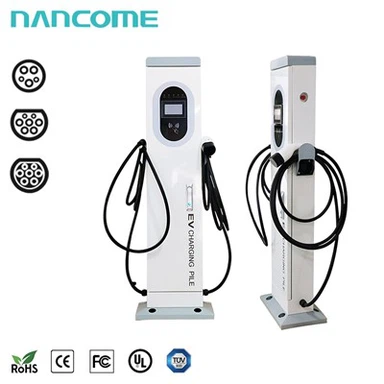
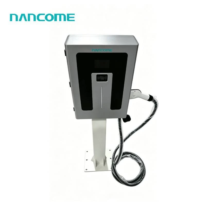
Our NEDF floor-mounted DC charging series includes 40, 60, 80, 120, 160, 180 and 240 kW configurations with a DC200–1000V output range. Connector options can include CCS1, CCS2, GB/T and CHAdeMO according to the destination market and target vehicles.
Standard dual-connector and project-specific multi-connector arrangements can be reviewed together with power sharing, OCPP integration, communication, cable requirements and outdoor installation conditions before production.
Commercial Parking
Match customer traffic and operating requirements to a commercial DC EV charging station.
Shopping Centers
Coordinate charging duration with retail dwell time using a shopping mall EV charger.
Dual Charging Bays
Review simultaneous access and power allocation for a dual-connector DC fast charger.
Connected Operation
Specify backend functions for an OCPP DC EV charger.
European Vehicles
Confirm voltage, cable and vehicle requirements for a CCS2 DC charger.
North American Vehicles
Review project compatibility for a CCS1 DC charger.
Buyer Questions
Parking-Lot DC EV Charging Station FAQ
Start with the charging operation: target vehicles, peak arrivals, energy per session, parking duration and service expectations. These inputs determine whether DC fast charging is appropriate and how many ports and how much power the site requires.
They should be positioned where target vehicles can enter, connect and leave without obstructing circulation. The location must also account for electrical routes, cable reach, accessible charging, drainage, impact protection, cooling airflow and maintenance access.
The number should be calculated from peak simultaneous demand, session occupancy, acceptable waiting time, equipment availability and growth. Daily vehicle totals alone do not show how many charging ports are required during the busiest period.
No. Charger output should match vehicle acceptance, required energy, parking duration and site capacity. A higher rating may provide little benefit if vehicles cannot use it or if the site controller must substantially limit simultaneous output.
Possibly, but an electrical assessment must confirm existing load, spare transformer and switchgear capacity, feeder routes, protection requirements and utility limits. Load management may help control demand but does not remove the need for engineering review.
Remote monitoring is valuable for reviewing availability, sessions, communication status and reported faults, especially at unattended or multi-site parking facilities. Required functions and backend interoperability should be confirmed before ordering.
Please provide the destination country, parking-lot type, target vehicles, charger quantity, required power, connector standards, available electrical supply, simultaneous-session requirement, communication method, backend, payment or authorization functions, installation environment and OEM requirements.
Review the Parking Layout Before Ordering the Chargers
Send us your parking-lot plan, vehicle types, peak charging demand, parking duration, available site power, connector standards and required network functions. We can review the charger configuration against the proposed bays and operating requirements.
Request a Parking-Lot Charging Review