


Why Power Modules Matter in a DC EV Charging Station
Sep 15, 2026
DC Charger Power Conversion
Why Power Modules Matter in a DC EV Charging Station
Power modules are the conversion building blocks inside a DC EV charging station. They convert incoming AC electricity into the controlled DC voltage and current requested by the vehicle. Their output range, efficiency, thermal performance, control accuracy and replaceability directly affect charger power, vehicle compatibility, energy losses and maintenance.
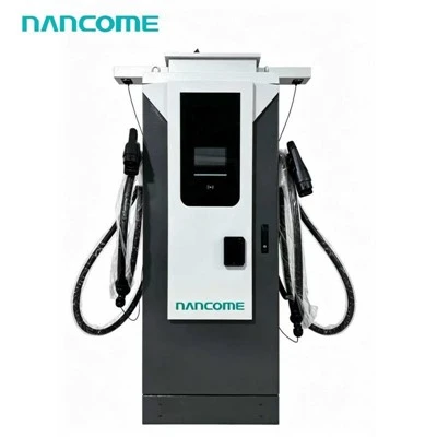
A charger cabinet rated at 120kW, 180kW or 240kW normally combines multiple modules under one controller. The cabinet rating alone does not show how those modules behave. Buyers should confirm individual module rating, installed quantity, power allocation, voltage range, cooling method, redundancy behavior and field-replacement procedure.
Core Function
From Grid AC to Vehicle-Controlled DC
The vehicle battery requires controlled DC power, while the charging site normally supplies AC power. Power modules perform the conversion and adjust their output in response to commands from the charger control system.
During a session, the requested voltage and current can change continuously. The installed modules must operate together within the limits of the vehicle, connector, cable, cabinet and electrical supply.
- Convert AC input into regulated DC output.
- Respond to changing voltage and current commands.
- Share load across multiple installed modules.
- Report status, temperature and fault conditions.
- Reduce or stop output when protection requires it.
Power Conversion Path
How Modules Participate in a Charging Session
The vehicle requests power within its permitted charging conditions, while the charger supplies the requested value only if it remains within the charger, module, cable and site limits.
Module Specifications
Parameters That Influence Charger Performance
| Module Parameter | What It Describes | Why It Matters |
|---|---|---|
| Rated output power | Maximum module output under defined operating conditions | Helps determine how many modules are required for the cabinet rating. |
| Output-voltage range | DC voltage the module can regulate | Must cover the operating voltage of target vehicles. |
| Output-current limit | Maximum permitted current under applicable conditions | Can restrict power at lower vehicle-battery voltages. |
| Efficiency | Share of input energy converted into usable DC output | Affects site energy use and the heat that must be removed. |
| Power factor | How effectively AC input current is used | Influences the charger's relationship with the electrical supply. |
| Cooling method | How conversion heat is transferred away from the module | Affects sustained output, cabinet design and maintenance. |
| Communication and diagnostics | Status, measurements and faults available to the controller | Supports load allocation, alarms and technical diagnosis. |
Cabinet Power
Module Quantity Builds the Charger Rating
A modular charger combines a defined number of compatible conversion modules. The exact module power and quantity vary by charger architecture, so the following values are illustrative rather than universal product specifications.
| Illustrative Cabinet Rating | If Using 20kW Modules | If Using 30kW Modules | Procurement Check |
|---|---|---|---|
| 60kW | 3 modules | 2 modules | Installed module rating and output envelope |
| 120kW | 6 modules | 4 modules | Single-port and dual-port allocation |
| 180kW | 9 modules | 6 modules | Sustained output and fault behavior |
| 240kW | 12 modules | 8 modules | Cabinet cooling, cable limit and site demand |
The complete charger may still be limited by module voltage and current, connector rating, cable capacity, cooling conditions, power-sharing logic or the site electrical limit.
Voltage and Current
The Same Kilowatt Rating Can Behave Differently Across Vehicles
Power is the product of voltage and current. A module may have sufficient rated kilowatts but still be unable to maintain that power at every point in its output-voltage range.
| Vehicle Condition | Module Requirement | Possible Limitation |
|---|---|---|
| Lower-voltage battery | More current is required to deliver the same power. | Module, cable or connector current limit may reduce output. |
| Higher-voltage battery | The module must support the vehicle's requested voltage. | Insufficient maximum output voltage prevents compatibility. |
| Battery near high state of charge | Output follows a decreasing vehicle-current request. | Vehicle charging-curve tapering controls the session. |
| Cold or hot battery | Output follows the vehicle's protective request. | The battery management system may restrict power. |
| Rapidly changing request | Voltage and current must be regulated accurately. | Control response and communication must remain coordinated. |
A single maximum voltage and maximum power value cannot show whether rated power is available at the operating voltage of every target vehicle.
Vehicle Compatibility
Wide-Voltage Modules Support a Broader Vehicle Mix
Passenger EVs
The module system must cover common passenger-vehicle battery voltages and changing session requests.
Electric Vans
Commercial duty cycles may require predictable energy delivery within a fixed operating window.
Electric Buses
Larger batteries and scheduled operation can require sustained module output and effective power allocation.
Electric Trucks
High energy demand makes vehicle voltage, current and sustained charging capability particularly important.
Mixed Public Traffic
The installed modules should support different vehicle voltages without relying on one reference model.
Future Vehicles
A suitable voltage range can help the charger serve changing vehicle platforms over its operating life.
Efficiency and Heat
Conversion Losses Become a Cooling Load
Power that is not delivered as useful DC output appears mainly as heat and auxiliary consumption. At high charger power, a small efficiency difference can represent a meaningful thermal load.
| Module Performance Area | Operational Effect | Buyer Evaluation |
|---|---|---|
| Conversion efficiency | Affects electrical losses and heat production. | Request efficiency conditions across representative loads and voltages. |
| Part-load operation | Efficiency may differ when only some output is required. | Review likely operation, not only the rated-power point. |
| Standby strategy | Unnecessary active modules can add auxiliary consumption. | Confirm whether modules are activated according to demand. |
| Load distribution | Uneven module loading can create temperature differences. | Confirm load-sharing and module-rotation logic. |
| Thermal derating | Available output falls when module temperature approaches a limit. | Request sustained-output and derating conditions. |
Review how chargers manage module and conductor temperature in high-power DC charger heat management.
Dynamic Power Allocation
Modules Determine How Flexibly Power Can Be Shared
In a multi-connector charger, the controller assigns available modules or module output to active sessions. The size of each allocation step and the control architecture influence how closely cabinet power can follow vehicle demand.
| Operating Condition | Module-Control Task | Effect on Charging |
|---|---|---|
| One active connector | Assign available capacity within connector and vehicle limits. | One vehicle may access most or all configured cabinet power. |
| Second vehicle connects | Divide available capacity between two sessions. | Power per vehicle may decrease according to the allocation rule. |
| One vehicle requests less power | Release unused capacity for another session where supported. | The second vehicle may receive additional output. |
| One session ends | Reassign available modules or output. | Remaining sessions may receive more power. |
| One module becomes unavailable | Remove the affected module and recalculate available power. | Sessions may continue at a reduced cabinet limit. |
A 120kW dual-port cabinet may provide up to 120kW to one vehicle or divide available capacity between two sessions. Confirm the exact allocation logic for the proposed configuration.
For multi-vehicle projects, review how a dual-gun DC charger assigns its available power.
Modularity and Availability
A Module Fault Does Not Always Disable the Entire Charger
| Module Event | Possible Charger Response | Operational Meaning |
|---|---|---|
| One module reports a fault | Isolate the affected module where the design supports it. | The charger may continue with a lower maximum output. |
| One module overheats | Reduce its load or remove it from active service. | Available power may decrease until inspection or recovery. |
| Communication with a module is lost | Stop using the unconfirmed power source. | Other modules may remain available. |
| Several modules fail | Continue at a significantly reduced rating or stop. | The result depends on minimum operating capacity and fault type. |
| Module is replaced | Identify, configure and test the replacement. | Compatibility and commissioning must be verified. |
Ask how much power remains after one module is unavailable, whether the charger automatically isolates it and how the backend reports the resulting capacity.
Maintenance and Replacement
Replaceability Affects Service Time and Spare-Parts Planning
Fault Identification
Module-level status helps technicians identify the affected conversion unit before arriving on site.
Physical Access
The cabinet should provide approved access for removal without disturbing unrelated components unnecessarily.
Electrical Isolation
Replacement requires a defined procedure for safely isolating and verifying the equipment.
Version Compatibility
Hardware and firmware compatibility must be confirmed before installing a replacement module.
Spare Inventory
Network operators should identify the correct module part number and recommended local spare quantity.
Return-to-Service Test
After replacement, verify communication, output sharing, cooling and fault-free charging under load.
High-voltage isolation, stored-energy control, compatibility checks and functional testing require qualified personnel following approved procedures.
Module Diagnostics
Data That Helps Explain Reduced Charger Output
| Diagnostic Information | Question Answered | Possible Action |
|---|---|---|
| Active module count | Are all installed modules available? | Investigate missing or isolated modules. |
| Module output | Are modules sharing load consistently? | Review control mapping and individual performance. |
| Module temperature | Is one module hotter than comparable units? | Inspect airflow, cooling contact and module condition. |
| Fault code and time | Which event reduced available capacity? | Follow the approved diagnostic procedure. |
| Input-voltage status | Is the supply affecting conversion operation? | Compare supply measurements with permitted limits. |
| Requested vs delivered output | Is low power caused by the vehicle or charger? | Separate vehicle demand from module capacity. |
A suitable remote monitoring DC charger configuration can help operators review module availability, charger output and reported faults.
Power Quality and Supply Coordination
Modules Also Shape the Charger's AC Input Behavior
The module system interfaces with both the vehicle and the site electrical supply. Its input characteristics must be considered when selecting transformers, switchgear, feeders and site operating limits.
| Electrical Area | Module Influence | Project Check |
|---|---|---|
| Input current | Active module quantity and load determine charger input demand. | Use the exact charger input specification. |
| Power factor | Module input control affects how current is drawn from the supply. | Confirm stated conditions and project requirements. |
| Harmonic performance | Switching conversion contributes to the site's nonlinear load profile. | Include the charger in the electrical designer's assessment. |
| Startup and sequencing | Modules may be activated progressively according to output demand. | Confirm behavior during energization and session start. |
| Site load management | Controller commands can limit or distribute active module output. | Test the charger with the intended site controller. |
Coordinate module and charger input data with the electrical infrastructure required for DC fast charging.
Procurement Checklist
Power Module Questions to Include in an RFQ
- What is the rating of one power module?
- How many modules are installed?
- What output-voltage range is supported?
- What current limit applies at low voltage?
- How is load shared among modules?
- How are modules assigned between connectors?
- Can one failed module be isolated?
- What power remains after one module fails?
- Which module data reaches the backend?
- How are the modules cooled?
- Can modules be replaced on site?
- Which spare module should be stocked?
The document should identify module rating, installed quantity, connector allocation, voltage and current limits, degraded operating modes and replacement compatibility.
Configurable Charging Hardware
Build Charger Power Around the Project Requirement
Our NEDF floor-mounted DC charging series covers 40–240kW with a DC200–1000V output range. Its modular configuration allows charger power and connector arrangements to be reviewed according to target vehicles, simultaneous sessions, available site power and future expansion.
Before production, we recommend confirming the required cabinet rating, target vehicle voltage, maximum connector current, single-port and dual-port output, module redundancy, cooling method, communication and backend requirements.
60kW Charging
Review moderate-power commercial requirements for a 60kW DC fast charger.
180kW Charging
Match module quantity and duty cycle to an 180kW DC charging station.
240kW Charging
Evaluate high-power module and cooling requirements for a 240kW DC fast charger.
Dual-Port Allocation
Confirm module sharing for a dual-connector DC fast charger.
Fleet Deployment
Coordinate available output with a fleet EV charging station schedule.
Complete Range
Compare available configurations in our DC EV charging station range.
Buyer Questions
DC EV Charger Power Module FAQ
It converts incoming AC electricity into controlled DC voltage and current for the vehicle. Multiple modules can operate together to create the charger's total available output.
The quantity depends on the cabinet rating and individual module power. For example, a 120kW cabinet could use six 20kW modules or four 30kW modules, but the actual architecture must be confirmed with the manufacturer.
It may continue at reduced power if the design can isolate the affected module and the fault does not require a complete shutdown. This degraded operating behavior should be verified for the exact charger.
No. Additional modules increase available cabinet power, but charging remains limited by the vehicle request, connector and cable capacity, module output envelope, cooling system and site power limit.
The module system must regulate the voltage requested by the vehicle. A wide suitable range helps the charger serve different battery platforms, but current limits must also be checked to confirm available power at each voltage.
Many modular chargers are designed for field replacement by qualified personnel. The correct part number, hardware and firmware compatibility, isolation procedure and post-replacement testing must be confirmed.
Confirm individual module rating, installed quantity, output-voltage range, current limits, cooling method, load-sharing logic, connector allocation, degraded operation, remote diagnostics and replacement-module availability.
Specify Module Performance Before Selecting Cabinet Power
Send us your charger power, target vehicles, voltage range, maximum current, connector quantity, simultaneous output, site power and redundancy requirements. We can review the module and power-allocation configuration for the project.
Request a Power Module Configuration


