


Modular DC Fast Chargers: Benefits for Maintenance and Power Expansion
Sep 16, 2026
Scalable DC Charging Architecture
Modular DC Fast Chargers: Benefits for Maintenance and Power Expansion
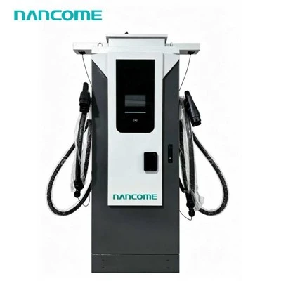
A modular DC fast charger builds its total output from replaceable power modules and coordinated subsystems. This architecture can simplify fault isolation, permit reduced-power operation after selected module faults and support staged power expansion when the cabinet, electrical supply, cooling system, cables and software are designed for the later capacity.
Modularity is most valuable when it is planned at the project stage. Adding power modules later is not automatically possible just because modules are removable. The charger must have spare module positions, compatible busbars and controls, adequate cooling, sufficient connector capacity and an electrical supply sized for the expanded load.
What Modular Means
Different Parts of a Charger Can Be Modular
The term "modular charger" often refers to its AC-to-DC power modules, but a project can also use modular communication, control, connector and site-power components.
Buyers should identify which assemblies can be replaced independently and which can be added later without changing the complete charger.
- Plug-in or field-replaceable power modules
- Separate connector and cable assemblies
- Replaceable control and communication units
- Expandable cabinet or power-block positions
- Site-level power cabinets serving multiple dispensers
Request a component map showing replaceable assemblies, installed power, vacant positions, maximum cabinet capacity and every condition required for expansion.
Operational Benefits
Why Modular Architecture Matters to Charging-Site Owners
Faster Fault Isolation
Module-level status can help technicians identify the affected conversion unit instead of treating the complete charger as one undivided assembly.
Reduced-Power Operation
Where the design permits, healthy modules can continue supplying limited power after one module is isolated.
Targeted Replacement
A qualified technician may replace an affected module without replacing the complete power-conversion system.
Staged Investment
A prepared cabinet may begin with lower installed power and receive additional compatible modules as demand increases.
Flexible Power Sharing
Available module capacity can be allocated between active connectors according to the charger control logic.
Simplified Spare Strategy
A network using common module types may maintain a focused stock of approved replacement units.
Maintenance Modularity
What Happens When One Power Module Develops a Fault?
| Fault Stage | Possible Charger Action | Maintenance Benefit |
|---|---|---|
| Fault detection | Record the affected module, event time and fault condition. | Provides a narrower starting point for diagnosis. |
| Module isolation | Remove the affected module from active power allocation where supported. | Prevents the fault from controlling healthy module output. |
| Reduced operation | Recalculate the charger's available power. | Selected charging service may continue before repair. |
| Remote diagnosis | Transmit module availability and fault information. | Helps prepare parts and instructions before dispatch. |
| Module replacement | Install an approved compatible module. | Avoids replacing unrelated power assemblies. |
| Return-to-service test | Verify communication, load sharing, output and cooling. | Confirms that full configured capacity is restored. |
Some faults require a complete shutdown for protection. Ask the supplier which module conditions permit degraded operation and which conditions stop the whole charger.
Capacity Expansion
Power Can Be Added in Planned Stages
Staged expansion can align charger investment with vehicle adoption. The initial project installs only the conversion capacity currently required while preparing the cabinet and site for a defined later rating.
Specify the initial and maximum future cabinet power before equipment selection.
Size the electrical, cooling, cable and control systems for the agreed expansion route.
Commission the lower power stage and document vacant positions and configuration.
Install compatible modules, update approved settings and test the expanded output.
The cabinet busbar, protection, module controller, cooling system, output contactors, connector cables and site feeder must all support the intended final rating.
Expansion Readiness
Every Supporting System Must Accommodate the Higher Power
| Expansion Area | Question to Confirm | Risk If Not Prepared |
|---|---|---|
| Module positions | Are physical slots, connectors and control addresses available? | Additional modules cannot be installed correctly. |
| Internal busbar | Is it rated for the final cabinet current? | Internal distribution becomes the power limit. |
| Cooling system | Can it remove heat at the expanded sustained load? | The charger may derate before reaching the new rating. |
| Connector and cable | Can each output path carry the intended voltage and current? | Cabinet power cannot be delivered to the vehicle. |
| Input protection | Are switchgear and protective devices suitable for final input demand? | Electrical equipment must be replaced during expansion. |
| Site supply | Can the transformer and utility connection support the added load? | The larger charger must remain software-limited. |
| Software configuration | Can the controller and backend recognize the new installed capacity? | Power allocation and reporting may be incorrect. |
Coordinate the future cabinet rating with the electrical infrastructure required for DC fast charging.
Illustrative Expansion
Example of Staged Module Installation
The following example uses 30kW modules to illustrate staged expansion. Actual module ratings, quantities and supported stages depend on the selected charger.
| Deployment Stage | Installed Modules | Illustrative Cabinet Power | Project Use |
|---|---|---|---|
| Initial stage | 2 × 30kW | 60kW | Lower initial demand or longer vehicle dwell times |
| Second stage | 4 × 30kW | 120kW | Increased session speed or dual-port demand |
| Third stage | 6 × 30kW | 180kW | Higher throughput for compatible vehicles |
| Final stage | 8 × 30kW | 240kW | Maximum planned cabinet capacity |
Confirm which ratings one cabinet supports, whether field expansion is approved and what hardware or software must be changed at each stage.
Module Compatibility
New Modules Must Match the Existing Charger
A module with the same nominal power is not automatically interchangeable. Mechanical, electrical, communication, thermal and firmware compatibility must all be confirmed.
| Compatibility Area | What Must Match | Why It Matters |
|---|---|---|
| Mechanical interface | Dimensions, rails, handles, locking and electrical connectors | The module must fit and connect without modification. |
| Input specification | Permitted voltage, phase arrangement and input behavior | Incorrect input compatibility can prevent safe operation. |
| Output envelope | Voltage range, current limit and power rating | Mixed capabilities can complicate power allocation. |
| Communication | Control protocol, addressing and diagnostic data | The charger controller must identify and command the module. |
| Firmware | Approved release and controller compatibility | Incompatible releases can affect load sharing and fault reporting. |
| Cooling arrangement | Airflow direction, heat-transfer interface and temperature limits | A physically fitted module still requires adequate cooling. |
Maintenance records should include manufacturer, model, rating, hardware revision, firmware version, installation position and replacement date.
Dual-Port Power Sharing
Modularity Makes Power Allocation More Flexible
| Charging Condition | Possible Module Allocation | Operational Benefit |
|---|---|---|
| One connector active | Assign available cabinet capacity to one session within output limits. | One compatible vehicle can use a larger share of installed power. |
| Two connectors active | Divide modules or combined output between both vehicles. | Two bays can operate simultaneously. |
| Unequal vehicle requests | Assign more capacity to the vehicle requesting higher power. | Reduces unused capacity where dynamic allocation is supported. |
| One vehicle begins tapering | Transfer released capacity to the other active session. | Improves use of installed module capacity. |
| One module is unavailable | Reallocate remaining power across active connectors. | Maintains partial charging service. |
If modules are assigned as complete fixed blocks, power may move between connectors in larger steps. Other designs may regulate combined output more gradually. Confirm the behavior required by the project.
For two-bay projects, specify the allocation logic of a dual-connector DC fast charger.
Expansion vs More Chargers
Adding Modules Is Not Always the Best Growth Strategy
| Growth Requirement | Add Modules to One Charger | Add Another Charger or Port |
|---|---|---|
| Faster individual sessions | Useful if target vehicles can accept the higher power. | May not improve power for the original vehicle. |
| More simultaneous vehicles | Helps only if additional connectors or dispensers are available. | Directly increases connection capacity. |
| Improved redundancy | Reduces the impact of a single module fault. | Reduces dependence on one cabinet or power group. |
| Limited parking space | Can increase output without another bay. | Requires suitable parking and equipment space. |
| Limited site power | Additional hardware may remain underused. | More access is possible through managed power sharing. |
Compare queueing, parking-bay demand, vehicle charging curves and failure resilience before concentrating additional power in one cabinet.
Thermal Planning
Additional Modules Create Additional Heat
Installing more conversion capacity increases the maximum heat that the cabinet may need to remove. Cooling equipment and site clearance must therefore be evaluated at the final planned rating.
Airflow Capacity
Fans, filters and internal passages must support the heat load produced by all installed modules.
Intake and Exhaust
The site layout must prevent obstruction and direct recirculation of discharged hot air.
Ambient Temperature
The expanded charger must maintain the required output under the project's maximum operating temperature.
Cable Heat
A higher cabinet rating may require a higher-current connector or a revised cable-cooling arrangement.
Thermal Derating
The charger should report when temperature reduces available module output.
Sustained Utilization
Expansion should be tested under repeated sessions, not only one short full-power test.
Review how DC fast chargers manage heat during high-power charging before approving a module expansion.
Commissioning an Expansion
Adding Modules Requires More Than Physical Installation
| Commissioning Check | Purpose |
|---|---|
| Confirm module identity and compatibility | Prevents unsupported hardware or firmware combinations. |
| Inspect physical and electrical connections | Confirms correct seating, locking and power connection. |
| Update approved cabinet configuration | Allows the controller to recognize the new capacity. |
| Verify upstream electrical ratings | Confirms that site infrastructure supports the expanded input. |
| Test module communication and load sharing | Shows that modules respond consistently to controller commands. |
| Test single-port and multi-port output | Verifies the intended power-allocation modes. |
| Monitor temperature under load | Confirms that cooling supports the new rating. |
| Update backend and asset records | Keeps reported capacity and maintenance records accurate. |
The work should be completed by qualified personnel using the supplier's approved parts, settings, inspection procedure and functional tests.
Procurement Checklist
Questions to Ask Before Buying a Modular Charger
- Which assemblies are field-replaceable?
- What is the power of one module?
- How many modules are installed initially?
- What is the maximum cabinet capacity?
- Which expansion stages are approved?
- Are vacant module positions fully prepared?
- What capacity remains after one module fails?
- Can healthy modules continue operating?
- How are modules shared between connectors?
- Which hardware changes during expansion?
- What recommissioning tests are required?
- How long will compatible modules remain available?
The proposal should show installed modules, vacant positions, initial output, maximum approved output, required upgrades and the parts needed for each expansion stage.
Configurable Modular Hardware
Plan Charger Power Around Present and Future Demand
Our NEDF floor-mounted DC charging series covers 40–240kW with a DC200–1000V output range. Its modular architecture supports different cabinet power and connector configurations according to target vehicles, simultaneous charging, available electrical capacity and project growth.
Before production, we recommend confirming the initial rating, required final rating, module expansion route, connector current, power-sharing logic, cooling capacity, site electrical supply, backend and spare-module strategy.
Commercial Deployment
Plan staged capacity for a commercial DC EV charging station.
Fleet Expansion
Coordinate future vehicle demand with a fleet EV charging station.
Dual-Port Allocation
Review module sharing for a dual-gun DC charger.
180kW Capacity
Match module quantity and duty cycle to an 180kW DC charging station.
240kW Capacity
Evaluate higher-power expansion for a 240kW DC fast charger.
Complete Product Range
Compare available configurations in our DC EV charging station range.
Buyer Questions
Modular DC Fast Charger FAQ
It is a charger whose output is built from separate power modules and whose selected assemblies can be serviced or configured independently. The exact replaceable and expandable components depend on the charger design.
No. Replaceable modules do not automatically create expansion capacity. The cabinet, busbar, cooling, connectors, protection, controls and site supply must all be designed for the higher rating.
It may continue at reduced power if the charger can isolate the affected module and the fault does not require a full protective shutdown. This behavior must be verified for the exact configuration.
Only combinations specifically approved by the charger manufacturer should be used. Modules must be compatible mechanically, electrically, thermally and through their control protocol and firmware.
Add modules when higher power per cabinet or vehicle is required and the infrastructure supports it. Add another charger or port when simultaneous vehicle access, queue reduction or cabinet-level redundancy is the primary goal.
Only if the existing transformer, switchgear, feeder and approved site capacity can support the higher charger input. Otherwise, the expanded charger must remain limited or the electrical infrastructure must be upgraded.
Please provide the initial and future charger power, vehicle voltage range, connector quantity, simultaneous output, available site capacity, expansion schedule, redundancy target, cooling conditions, backend requirements and preferred spare-parts strategy.
Define the Expansion Route Before Ordering the Cabinet
Send us your initial power, future power target, vehicle voltage range, connector quantity, simultaneous output, site capacity and expansion schedule. We can review the modular configuration and the infrastructure required for each stage.
Request a Modular Expansion Plan


