

Available Single-Vehicle Output
Confirm how much cabinet power either connector can access when the other bay is empty. A single active vehicle is still limited by its accepted power and the configured output current.

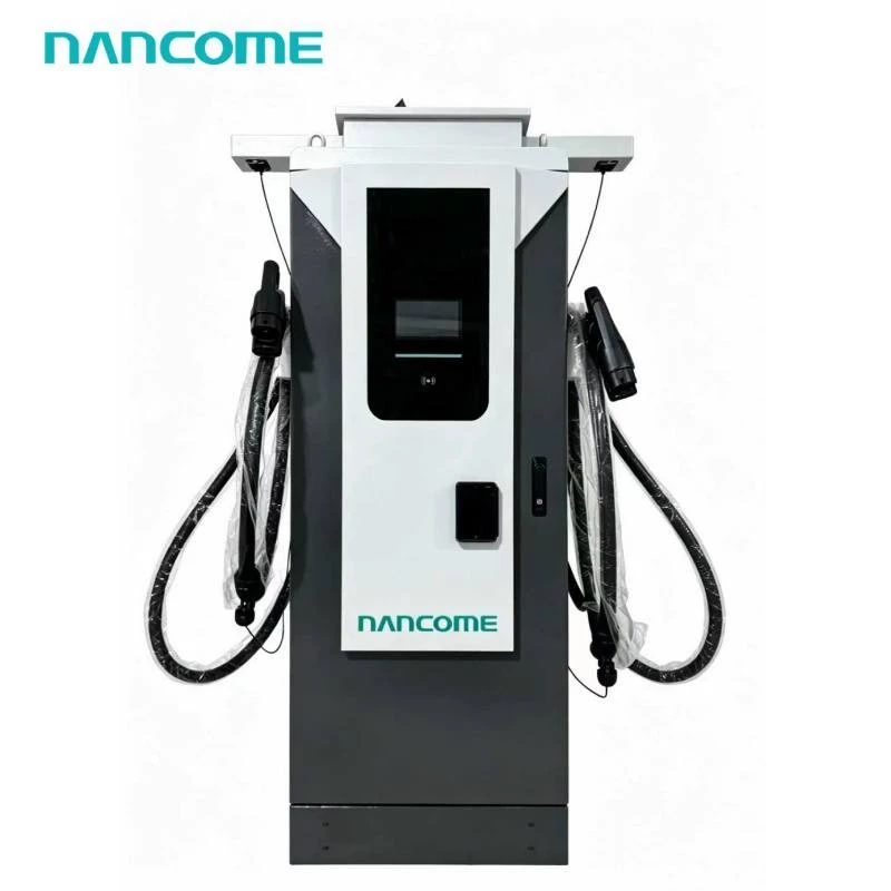
• Two CCS2 connectors for two charging positions • 40–240kW total cabinet power options • DC200–1000V output for compatible EV platforms • Standard 5m cables with optional length upgrades • IP54 floor-mounted cabinet for commercial sites • Optional OCPP for charging-network integration • OEM branding and project configuration available
Our Dual CCS2 DC Charger combines two CCS2 charging connectors in one floor-mounted cabinet. We offer configurations within our 40–240kW platform for sites serving compatible CCS2 vehicles.
The main purchasing decision is how much power each vehicle needs while both bays are occupied. Cabinet capacity, current limits and the ordered power-sharing arrangement determine the output available to each session.
Tell us the vehicles and charging window for each bay. We can review the two-output configuration against those requirements before quotation.
Review My Two-Bay RequirementTwo CCS2 connectors serve vehicles using the same interface, but those vehicles may request very different voltage and current. Define the expected operating behavior through the complete charging cycle.
Confirm how much cabinet power either connector can access when the other bay is empty. A single active vehicle is still limited by its accepted power and the configured output current.
Specify the required output for both sessions. The combined demand cannot exceed the available cabinet output, and the allocation need not be an equal split unless that behavior is specified.
Ask whether power released by one vehicle can be reassigned to the other. Dynamic redistribution must be confirmed for the selected hardware and control configuration.
We configure the CCS2 pair on our commercial floor-mounted platform. Series ranges are not guaranteed per-connector ratings; the final technical schedule identifies both output limits and simultaneous operation.
| Selection Item | Available Range | Order Definition |
|---|---|---|
| Total Cabinet Power | 40 / 60 / 80 / 120 / 160 / 180 / 240kW | Select by combined demand and site capacity |
| Connector Pair | CCS2 + CCS2 | Two compatible CCS2 vehicle connections |
| DC Voltage | DC200–1000V platform range | Confirm the required voltage range at each output |
| DC Current | 0–300A listed series range | Confirm per-connector and simultaneous limits |
| Power Allocation | Configuration-dependent | Define one-vehicle and two-vehicle output behavior |
| AC Input | AC380V ±20%; 3P + N + PE; 45–65Hz | Verify against the actual site supply |
| Cable Length | Standard 5m; optional length upgrades | State the required reach for each charging bay |
| Cooling | Air cooling; liquid cooling optional | Confirm the cable assembly and thermal configuration |
| Installation | Floor-mounted; IP54; indoor or outdoor | Coordinate foundation, drainage and service access |
| Operating Conditions | -20°C to 50°C; altitude ≤2000m | Provide site temperature and elevation |
| Humidity | 5–90% RH, non-condensing | Review condensation and local exposure conditions |
| Network Management | Remote operation; OCPP optional | Specify protocol version and backend requirements |
| OEM / ODM | Project customization available | Confirm branding, interface and packaging needs |
A shared power budget is only one part of the calculation. The current required at each vehicle's actual battery voltage must also fit the selected output and CCS2 cable.
The examples below are DC-side calculations using power = voltage × current. They illustrate purchasing requirements, not guaranteed operating modes or charging-time predictions.
| Illustrative Demand | Calculated DC Current | Configuration Requirement |
|---|---|---|
| 60kW + 60kW at 400V per vehicle | 150A per connector | 120kW combined output with both current demands supported |
| 90kW + 30kW at 400V per vehicle | 225A at A; 75A at B | 120kW total plus support for the requested unequal allocation |
| 120kW at 400V + 120kW at 800V | 300A at A; 150A at B | 240kW total, separate voltage control and suitable per-output current limits |
Check both parking directions and inlet positions. The standard cable length is not the same as usable reach after allowing for routing, connector handling and cabinet placement.
For networked operation, ask how the backend identifies each connector and its session. Specify the records needed for operator reconciliation and troubleshooting.
Include output interruption in the acceptance discussion. Do not assume that a fault or stop on one side always leaves the other session unaffected.
We use your vehicle, site and operator requirements to define the proposed configuration. Request a written acceptance schedule for the functions that matter to your deployment.
Specify maximum voltage, current and power for A and B, combined output, single-session limits and the required allocation behavior.
Define checks for A only, B only, both active, different vehicle voltage demands and one session ending while the other continues.
Confirm cables, cooling, OCPP functions, branding, documentation, packaging and purchase quantity. We confirm delivery terms against the agreed order scope.
No. If 120kW is the total cabinet rating, the combined output to both vehicles cannot exceed that available capacity. Maximum single-connector power and simultaneous allocation must be confirmed separately.
The platform's DC200–1000V range covers both nominal battery classes, but simultaneous charging at different voltages requires a suitable output architecture. Provide both vehicle models so independent voltage control and simultaneous current limits can be confirmed.
Only if the selected configuration supports that allocation behavior. Specify automatic redistribution as a requirement and confirm its operating limits before ordering. The remaining vehicle must also be able to accept the additional output.
That should not be assumed. The published figure describes the series range. Ask for the maximum current of each output and the limits that apply when both connectors operate simultaneously.
OCPP integration is optional. Include separate connector status, session identification and energy reporting in your backend requirements, then verify those functions with the selected charger configuration and management platform.
Not in every respect. A dual cabinet shares total power and may share control or protection components. Two separate chargers have a different equipment and fault arrangement. Compare simultaneous output, installation cost, maintenance access and required service continuity.
Send vehicle models, battery voltage, required power per vehicle, simultaneous charging demand, charging window, site supply, cable reach for both bays, backend requirements, destination, quantity and OEM needs.
Tell us what Vehicle A and Vehicle B need while charging together. We will review total cabinet power, per-output limits, cable configuration and backend requirements for your quotation.
Hot Tags: dual ccs2 dc charger, China dual ccs2 dc charger manufacturers, suppliers, factory, 22kw wallbox type 2 ev fast wall charger station, charger station ev 22kw wall mounted column, gbt ev charge with credit card payment, home ev charger wall mounted charging stations, new energy car charging 4 3 inch screen ev charger, smart electric vehicle charging station
(0/10)


