For Applicable Vehicle Fleets
Consider this combination when the verified vehicle population includes CCS1 and CHAdeMO inlets. Confirm current and future vehicle purchasing plans.
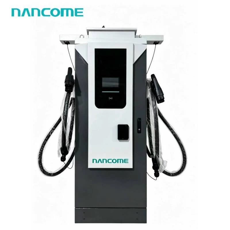
• CCS and CHAdeMO connectors in one cabinet • CCS1 or CCS2 selected for the target vehicle fleet • 40–240kW commercial power configurations • DC200–1000V output for varied battery platforms • Separate charging control for two vehicle standards • Optional OCPP for connector-level monitoring • OEM branding and project configuration available
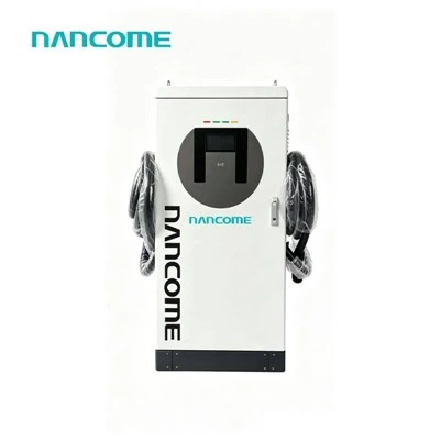
Our CCS CHAdeMO DC Charger combines one project-defined CCS connector with one CHAdeMO connector in a commercial floor-mounted cabinet. The CCS side must be specified as CCS1 or CCS2 according to the target vehicles.
This configuration suits locations where CCS adoption is growing but a measurable group of CHAdeMO vehicles still requires dependable charging access. The cabinet can support both vehicle groups without treating their connectors or communication protocols as interchangeable.
Before quotation, we confirm the exact CCS type, CHAdeMO vehicle demand, per-connector current and required simultaneous charging behavior.
Check a CCS + CHAdeMO SetupCCS1 and CCS2 are different vehicle interfaces. Writing only "CCS + CHAdeMO" in an RFQ leaves a critical part of the charger configuration unresolved.
Consider this combination when the verified vehicle population includes CCS1 and CHAdeMO inlets. Confirm current and future vehicle purchasing plans.
Consider this pairing where compatible CCS2 vehicles dominate new demand while operational CHAdeMO vehicles still require access.
The country name alone is insufficient. Provide the actual vehicle models and charging inlets before the connector pair is approved.
The connector pair can be configured on our NEDF commercial platform. The quotation and final technical schedule must identify the exact connector types, cable assemblies and output limits.
| Selection Item | Available Range | Order Confirmation |
|---|---|---|
| Rated Cabinet Power | 40 / 60 / 80 / 120 / 160 / 180 / 240kW | Select from combined demand and site capacity |
| Connector A | CCS1 or CCS2 | State the exact CCS interface |
| Connector B | CHAdeMO | Provide vehicle models and required current |
| DC Voltage Range | DC200–1000V platform range | Confirm the required range for each output |
| Series Output Current | 0–300A; configuration-dependent | Define the limit separately for both connectors |
| Simultaneous Charging | Project-specific configuration | State required output while both sides are active |
| AC Input | AC380V ±20% | Verify actual incoming site voltage |
| Input Connection | 3P + N + PE; 45–65Hz | Confirm site phases, frequency and grounding |
| Power Factor | ≥0.95 under normal output power | Confirm in the model-specific schedule |
| Cable Length | Standard 5m; optional upgrades | Define CCS and CHAdeMO cable reach separately |
| Cable Cooling | Air cooling; liquid cooling optional | Match cooling to the selected current and cable |
| Installation | Floor-mounted; indoor or outdoor | Coordinate foundation and service clearances |
| Protection Level | IP54 | Review actual outdoor exposure conditions |
| Operating Conditions | -20°C to 50°C; altitude ≤2000m | Provide site temperature and elevation |
| Humidity | 5–90% RH, non-condensing | Address condensation through site design |
| Management | Remote operation; OCPP optional | Specify backend and connector-level functions |
| Customization | OEM, ODM and project configuration | Confirm branding, language and packaging |
The CCS–CHAdeMO combination is most useful when two vehicle populations generate meaningful demand. Historical regional popularity alone does not show whether the pairing will be used at a particular site.
| Fleet Evidence | Configuration Implication | Information to Collect |
|---|---|---|
| CHAdeMO vehicles operate daily | A dedicated CHAdeMO connector may protect operational access | Vehicle count, daily sessions and required departure time |
| CHAdeMO demand is occasional | Compare access value with cable and maintenance scope | Monthly sessions and consequences of unavailable charging |
| New purchases primarily use CCS | Allocate more usable capacity to confirmed CCS demand | Fleet acquisition schedule and accepted CCS power |
| Legacy vehicles have retirement dates | Evaluate required service period before finalizing the asset | Retirement dates and replacement-vehicle interfaces |
| Public vehicle mix is uncertain | Use local registration, traffic or pilot-session data | Observed connector demand rather than broad market estimates |
Confirm the maximum voltage, current and power available through the selected CCS1 or CCS2 cable while the CHAdeMO side is idle.
Confirm the corresponding limits for the CHAdeMO connector rather than assuming they equal the CCS-side rating.
Define the minimum acceptable power for both vehicles and whether unused capacity must be reassigned when either vehicle reduces its demand.
The CCS and CHAdeMO connectors use different vehicle communication paths. Acceptance should cover both individually and in the simultaneous operating conditions required by the project.
Verify connection, communication, start, regulated output, normal stop and disconnection with the specified CCS interface.
Verify the equivalent operating sequence using a representative compatible CHAdeMO vehicle or agreed test method.
Check the specified power limits while both connector types operate, including changing vehicle demand.
Agree how a vehicle fault, connector fault or stopped session on one side affects the other active charging path.
Optional OCPP can support integration with a compatible management platform. The backend should distinguish the CCS and CHAdeMO connectors rather than treating the cabinet as one undifferentiated charging point.
Select CCS1 or CCS2 from the actual charging inlets on the target vehicles. The destination country can guide the review, but it does not replace a model-by-model compatibility check.
Simultaneous operation can be reviewed for the selected project configuration. State the minimum power required by both vehicles and confirm the combined output, current limits and allocation behavior.
Not when both sessions require power unless the system is specifically configured for the combined demand. Confirm the single-output maximum and simultaneous output available to each connector.
No direct compatibility should be assumed. CCS and CHAdeMO use different connectors and communication systems. Each vehicle should use the compatible charging output defined for its inlet.
It may be justified when compatible vehicles generate regular or operationally important demand. Review current sessions, fleet retirement dates and replacement-vehicle plans before fixing the connector mix.
OCPP is optional. Include connector identity, status, session and energy reporting in the requirements, then verify those functions with the selected backend before deployment.
Send the destination country, exact CCS type, CCS and CHAdeMO vehicle models, battery voltages, required power, simultaneous charging demand, site input, cable reach, OCPP platform, quantity and OEM requirements.
Send the CCS type, target vehicles, demand for each connector, simultaneous output, site supply and backend requirements. We will review the two-standard configuration for quotation.
Hot Tags: ccs chademo dc charger, China ccs chademo dc charger manufacturers, suppliers, factory, 30kw ev dc gb t charger, commercial electric car charging station, Dc Charger For Electric Car with Cable, ev charging station for india dc, ev fast wall car charger box, Plug and Play Dc EV Charging Station
(0/10)