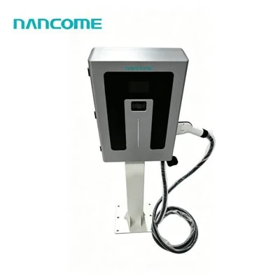
Charging Connector and EV Communication
CCS1, CCS2, GB/T or CHAdeMO is selected according to the vehicle fleet. OCPP does not replace the vehicle charging interface.


• Optional OCPP 1.6J backend communication • 40–240kW commercial DC power configurations • DC200–1000V supports varied battery platforms • CCS1, CCS2, GB/T and CHAdeMO options • Connector-level status and session reporting • Third-party backend testing before deployment • OEM branding and interface customization
Our OCPP 1.6 DC Charger can be configured with OCPP 1.6J communication for connection to a compatible charging-station management system. Available DC charger configurations cover 40–240kW and DC200–1000V.
Specifying OCPP 1.6 alone does not guarantee complete interoperability. The charger and backend must agree on connection settings, implemented functions, connector numbering, authorization, transaction handling and recovery after network interruption.
Provide the selected backend and required operating workflow before production so the integration scope can be reviewed and tested.
Check Backend CompatibilityCCS1, CCS2, GB/T or CHAdeMO is selected according to the vehicle fleet. OCPP does not replace the vehicle charging interface.
The charger manages its configured power output, connector status, session operation and local protection functions.
OCPP exchanges supported charger status, authorization, transaction, meter and remote-operation messages with the selected management platform.
OCPP 1.6J is available as an optional communication configuration. The final quotation must identify the charger hardware, network connection, backend implementation and functions included in the project.
| Selection Item | Available Specification | Project Confirmation |
|---|---|---|
| OCPP Version | Optional OCPP 1.6J | Confirm the version required by the backend |
| Rated Cabinet Power | 40 / 60 / 80 / 120 / 160 / 180 / 240kW | Match vehicle demand and site capacity |
| DC Output Voltage | DC200–1000V platform range | Confirm target vehicle voltage |
| Series Output Current | 0–300A; configuration-dependent | Confirm the limit for each connector |
| Connector Options | CCS1 / CCS2 / GB/T / CHAdeMO | Select from actual vehicle inlets |
| Connector Quantity | Two standard; project options available | Define Connector ID mapping and simultaneous use |
| AC Input | AC380V ±20% | Verify the actual site supply |
| Input Connection | 3P + N + PE; 45–65Hz | Confirm phases, frequency and grounding |
| Power Factor | ≥0.95 under normal output power | Confirm in the model schedule |
| Charging Cable | Standard 5m; optional length upgrade | Define reach for every bay |
| Cooling | Air cooling; liquid cooling optional | Match the selected current and cable |
| Installation | Floor-mounted; indoor or outdoor | Coordinate site and service clearances |
| Protection Level | IP54 | Review actual environmental exposure |
| Operating Conditions | -20°C to 50°C; altitude ≤2000m | Provide site temperature and elevation |
| Humidity | 5–90% RH, non-condensing | Address condensation in site design |
| Remote Operation | Configuration-dependent | List every required remote command |
| Customization | OEM, ODM and project configuration | Confirm branding, language and packaging |
Define the connector states, fault information and heartbeat behavior required by the management platform.
State how RFID, applications, fleet accounts or other user workflows obtain backend authorization.
Agree how charging starts, stops and records transaction identifiers, timestamps and delivered energy.
List required remote start, remote stop, reset or other commands rather than assuming every optional function is included.
A dual-connector DC charger must expose clear connector identities to the backend. Incorrect mapping makes remote commands, status records and transaction reports difficult to reconcile with the physical charging bay.
| Mapping Element | Definition Required | Acceptance Check |
|---|---|---|
| Charge Point Identity | Unique identity recognized by the backend | Charger connects to the assigned platform record |
| Connector 1 | Physical cable, charging standard and bay | Status and commands match the correct cable |
| Connector 2 | Physical cable, charging standard and bay | Transactions remain separate from Connector 1 |
| Status Reporting | Required operating and fault states | Backend display matches actual charger condition |
| Meter Data | Values, units and reporting interval | Received values match the agreed test session |
| Remote Control | Permitted command for each connector | Command affects only the intended session |
Define whether new users can be authorized while the backend is unavailable and which local authorization rules apply.
Specify whether an existing charging session continues, stops or follows another project-defined response after communication loss.
Agree how transaction and meter records are retained and reported after the charger reconnects to the platform.
Confirm the endpoint, charge point identity, authentication settings and network environment.
Check charger registration, heartbeat and connector status on the selected backend.
Test authorization, start, meter reporting, stop and transaction records for every connector.
Review connection loss, rejected authorization, interrupted sessions, faults and reconnection behavior.
OCPP 1.6J may suit an established platform when the required charger messages and operating workflows are already defined.
Confirm the platform roadmap before fixing the protocol version. Newer OCPP versions are not automatically backward-compatible with OCPP 1.6.
Separate protocol support, certification requirements, implemented functions, security settings and backend acceptance testing in the purchase specification.
It is a DC charger configured to communicate with a compatible central management system using an OCPP 1.6 implementation. The project should specify OCPP 1.6J and the required backend functions.
Interoperability should not be assumed from the version name alone. Implemented functions, connection settings, security requirements and vendor-specific backend behavior must be reviewed and tested.
A dual-connector configuration can report connector-specific status and transactions when the mapping and required messages are implemented. Both physical cables should be checked against their backend Connector IDs.
Remote start and stop can be included when supported by the charger configuration and backend workflow. State these commands explicitly and test them for each connector before deployment.
The required offline behavior must be defined for authorization, active sessions, local records and later synchronization. Do not leave these decisions until the charger is installed.
No. They are different protocol versions, and OCPP 2.0.1 is not automatically backward-compatible with OCPP 1.6. Select the version required by the intended management platform.
Send the backend provider, OCPP transport, endpoint requirements, charger identity format, connector quantity, required messages, authorization and payment workflow, offline behavior, charger power, vehicle standards, site supply, quantity and destination.
Send the OCPP 1.6 platform, required commands, connector mapping, offline rules, charger power and vehicle interfaces. We will review the hardware and integration scope for quotation.
Hot Tags: ocpp 1.6 dc charger, China ocpp 1.6 dc charger manufacturers, suppliers, factory, charging dc station for electric car, commercial electric car charging station, Dc Charger For Electric Car with Cable, Dc Fast EV Charging Stations, ev fast wall car charger box, home electric car charger ev charging station app
(0/10)