

Highway Sites
Serve intercity drivers who need substantial energy during a short stop and whose vehicles support higher DC charging power.

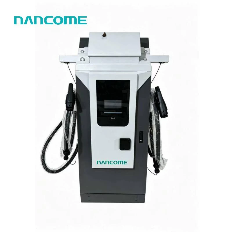
200kW project configuration for high-throughput commercial DC charging sites
DC200–1000V output platform supports 400V and 800V vehicle architectures
Dual charging connectors support flexible single-vehicle or shared-power operation
Up to 300A standard platform output requires voltage matching for full 200kW delivery
IP54 floor-mounted enclosure supports indoor and outdoor commercial installations
Remote operation, OCPP integration and OEM configuration available by project
Power modules, connector current and allocation logic confirmed before production
A 200kW DC fast charger is intended for commercial sites where vehicle turnaround and charging-bay utilization directly affect daily operations. Reaching the full rated power depends on the vehicle battery voltage, accepted charging current, connector capacity and approved power-module configuration.
A 200kW label does not mean every connected vehicle can receive 200kW.
The business case is strongest when the site serves high-power vehicles, has sufficient grid capacity and needs shorter charging-bay occupancy.
Serve intercity drivers who need substantial energy during a short stop and whose vehicles support higher DC charging power.
Reduce charging windows for commercial vehicles operating on fixed dispatch, return and turnaround schedules.
Add higher-power capacity to busy public networks where charger availability and sessions per bay affect revenue.
Support airports, terminals and logistics locations with steady traffic and vehicles capable of using high DC power.
DC charging power is approximately the product of charging voltage and current. A lower-voltage vehicle requires more current to receive the same power.
| Vehicle-Side Voltage | Current Needed for 200kW | Power at 300A | Configuration Implication |
|---|---|---|---|
| 400V | Approximately 500A | Approximately 120kW | Higher-current system required |
| 500V | Approximately 400A | Approximately 150kW | Current exceeds 300A |
| 667V | Approximately 300A | Approximately 200kW | Near target at 300A |
| 800V | Approximately 250A | Approximately 240kW | 200kW technically achievable |
Values are simplified voltage × current calculations for preliminary selection. Actual charging power varies with vehicle requests, battery state, temperature, cable limits, conversion losses and charger control.
A site serving mainly lower-voltage vehicles may not obtain the expected benefit from a standard 300A configuration.
Model names alone may be insufficient because battery and charging specifications can vary by model year and destination market.
Provide the charging-inlet standard, nominal battery voltage and maximum accepted DC current whenever available.
Connector quantity and simultaneous charging logic must be defined separately from the total cabinet power.
Available cabinet power is directed to one connector when the operating goal is the shortest practical charging session.
The output remains limited by vehicle voltage, accepted current, connector rating and the approved charger configuration.
Total cabinet output is distributed between two connected vehicles according to fixed or dynamic power-allocation rules.
Provide the required minimum power per connector, priority logic and expected vehicle mix before quotation.
Published product-family values are separated from 200kW-specific items that require engineering approval.
| Category | Item | Specification | Order Status |
|---|---|---|---|
| Rated power | Cabinet output | 200kW project configuration | Engineering confirmation |
| AC input | Voltage range | AC380V ±20% | Product platform |
| AC input | Connection | 3P + N + PE | Product platform |
| AC input | Frequency | 45–65Hz | Product platform |
| AC input | Power factor | ≥0.95 at normal output power | Product platform |
| DC output | Voltage range | DC200–1000V | Product platform |
| DC output | Current range | 0–300A standard platform | Check against vehicle voltage |
| Connection | Charging connectors | 2 connectors; project platform supports expansion up to 4 | Select quantity and standard |
| Cable | Length | Standard 5m; optional upgrade available | Confirm parking reach |
| Cooling | System | Air cooling; liquid cooling optional | Select by current demand |
| Environment | Operating temperature | -20°C to 50°C | Product platform |
| Environment | Storage temperature | -40°C to 85°C | Product platform |
| Environment | Humidity | 5–90% RH, non-condensing | Product platform |
| Environment | Altitude | ≤2000m | Product platform |
| Enclosure | Protection | IP54 | Product platform |
| Installation | Structure | Floor-mounted; indoor or outdoor | Product platform |
| System | Remote operation | Supported | Define required functions |
| Customization | OEM / ODM | Project-based customization available | Submit customization scope |
A high-power DC charger must be evaluated together with transformers, buildings, other chargers and future expansion loads.
Request a Site Configuration ReviewConfirm mounting, cable entry, drainage and protective barriers before completing civil work.
Check the distance from the cabinet to vehicle inlets for every expected parking orientation.
Keep sufficient access for airflow, power-module replacement and electrical maintenance.
Position bollards and wheel stops to protect the cabinet without blocking cable handling.
Protocol support and complete platform compatibility are not the same. Required functions should be tested against the intended charging-management system.
The approved quotation should state the module configuration, connector-current limit, cable arrangement, power-distribution logic and communication scope.
MOQ, lead time, destination-market certification and shipping terms are confirmed according to the final order specification.
Technical points to settle before selecting modules, connectors and site infrastructure.
A vehicle charging at 400V would require approximately 500A to receive 200kW. With a 300A output limit, theoretical power at 400V is approximately 120kW. A higher-current connector, cable and charger configuration would be required for 200kW at this voltage.
In simplified electrical terms, 200kW at 800V requires approximately 250A. The vehicle must still request this power, and the connector, charger configuration, battery condition and charging curve must permit it.
The 200kW configuration requires project review because the published standard power list does not separately identify this rating. Module quantity, output current, cooling and power-allocation logic must be approved before production.
The dual-connector platform can be configured for project-specific operation. Confirm whether you need single-vehicle priority, fixed power sharing or dynamic allocation between two connected vehicles.
The choice depends on required connector current, cable length, ambient conditions, duty cycle and vehicle voltage. Higher-current operation may require a different cable and cooling configuration than a 300A standard platform.
Provide the required OCPP version, backend platform, communication method, authentication workflow, payment process, remote commands, fault reporting and firmware-management requirements.
Include the site supply, transformer capacity, vehicle models, battery voltages, connector standards, simultaneous charging requirement, cable reach, OCPP platform, quantity, destination country and OEM requirements.
Send the vehicle voltage and current limits, site supply, transformer capacity, connector standards, charging-bay layout, OCPP platform, quantity and destination country.
Hot Tags: 200kw dc fast charger, China 200kw dc fast charger manufacturers, suppliers, factory, charging dc station for electric car, commercial electric car charging station, Dc Charger For Electric Car with Cable, Dc Fast Charger For Home with Color Display, home electric car charger ev charging station app, new energy car charging 4 3 inch screen ev charger
(0/10)


