


How Load Balancing Improves DC EV Charging Efficiency
Aug 25, 2026
Smart Power Management
How Load Balancing Improves DC EV Charging Efficiency
Load balancing distributes a site's available electrical capacity among active DC charging sessions instead of allowing every charger to demand maximum power at the same time. It can serve more charging bays within a defined site limit, reduce coincident peak demand and direct power toward vehicles with the most urgent operational needs.
Load balancing improves site-level efficiency; it does not increase an EV's maximum charging acceptance or the electrical conversion efficiency of an individual charger.
The Operating Principle
One Site Limit, Multiple Changing Power Requests
The power requested by an EV changes throughout a charging session. The vehicle's battery management system may accept high power at one state of charge and request less power as the battery fills or its temperature changes.
At the same time, the building may have elevators, cooling equipment, lighting or production loads drawing from the same electrical connection. A load-management controller monitors these conditions and assigns an appropriate limit to each charger.
- Site import capacity defines the total power boundary.
- Building load changes the capacity available for charging.
- Connected vehicles report their charging requirements.
- Operating rules determine how available power is divided.
- Charger output is adjusted as conditions change.

Efficiency Gains
Where Load Balancing Creates Practical Value
Higher Infrastructure Utilization
A site can operate several charging bays without reserving every connector's full nameplate power simultaneously. The installed electrical capacity is shared according to actual demand.
Controlled Peak Demand
Charging output can be reduced when the building approaches its import limit or during a designated peak period, helping the operator avoid uncontrolled coincident demand.
More Useful Charging Bays
Instead of concentrating the budget on a small number of fully powered bays, a project may support more connectors and distribute power as vehicles arrive and leave.
Priority-Based Dispatch
Fleet departure time, required energy, current state of charge or service class can inform which vehicle receives more power when capacity is constrained.
Phased Site Expansion
Software-managed limits can support an initial deployment while preserving a practical route for adding chargers, connectors or electrical capacity later.
Clearer Energy Data
Central monitoring can record site demand, charger output and session behavior, giving operators evidence for revising limits and future capacity planning.
Illustrative Allocation
How Available Power Can Move Between Charging Bays
Consider a site with a 240 kW charging limit and four active connectors. The controller can change the allocation without exceeding that limit. The figures are illustrative control examples rather than promised charging rates.
| Operating Condition | Bay A | Bay B | Bay C | Bay D | Site Total |
|---|---|---|---|---|---|
| One urgent vehicle | 120 kW | 60 kW | 30 kW | 30 kW | 240 kW |
| Equal service policy | 60 kW | 60 kW | 60 kW | 60 kW | 240 kW |
| Bay A enters taper | 30 kW | 90 kW | 60 kW | 60 kW | 240 kW |
| Building load increases | 30 kW | 60 kW | 45 kW | 45 kW | 180 kW |
Actual allocation depends on charger architecture, vehicle acceptance, connector use, minimum operating limits, site capacity and the selected control policy.
Control Strategies
Static, Dynamic and Priority-Based Load Balancing
| Strategy | How It Works | Best-Fit Environment | Main Limitation |
|---|---|---|---|
| Static allocation | Each charger or group receives a predetermined power limit. | Small sites with stable building demand and predictable use. | Unused capacity may remain unavailable to another active charger. |
| Dynamic site balancing | Charging capacity changes in response to measured building and charger demand. | Hotels, commercial properties and mixed-use facilities. | Requires compatible meters, controls and communication. |
| Equal sharing | Available charging power is divided among active connectors. | Public parking where users have similar service priority. | It may not reflect different departure times or energy needs. |
| Priority dispatch | Selected vehicles, routes or user groups receive more power. | Fleet depots, bus operations and logistics sites. | Reliable scheduling data and clear operating rules are necessary. |
| Time-based control | Charging limits change by tariff period or operating schedule. | Sites with predictable dwell time and time-varying electricity costs. | Unexpected vehicle demand may require manual or automatic overrides. |
Application Logic
The Allocation Policy Should Match the Site
Fair distribution, queue conditions and vehicle acceptance can guide allocation while preserving a clear customer experience.
Required departure time and route energy normally matter more than equal power at every connector.
Charging demand should remain coordinated with guest rooms, kitchens, heating, cooling and other building loads.
Fast turnover and unpredictable arrivals require enough site capacity before software allocation is used to manage temporary concurrency.
Hardware and Software
What a Load-Balanced DC Charging System Needs
Site-Level Metering
A suitable meter or energy-management input must provide dependable information about the load boundary being controlled.
Controllable Chargers
The charging equipment must accept power limits and report operational status with enough consistency for the selected control strategy.
Communication Network
Ethernet, cellular or another project-approved connection may link chargers, meters, local controllers and the central platform.
Control Platform
A local controller or charging management system applies site limits, priority rules and fallback behavior.
Defined Fail-Safe Limits
The project should specify charger behavior during meter, network or platform communication loss so the electrical limit remains protected.
Commissioning Tests
Testing should cover simultaneous sessions, changing building demand, charger disconnection, reconnection and communication failure.
Optional OCPP can support communication between compatible chargers and a central management system. Buyers should confirm the protocol version, required smart-charging functions and backend interoperability instead of treating "OCPP supported" as a complete load-management specification. The Open Charge Alliance identifies Smart Charging as a distinct certification profile within its OCPP 2.0.1 certification program.
Charger Configuration
Match Power-Sharing Capability to Vehicle Demand
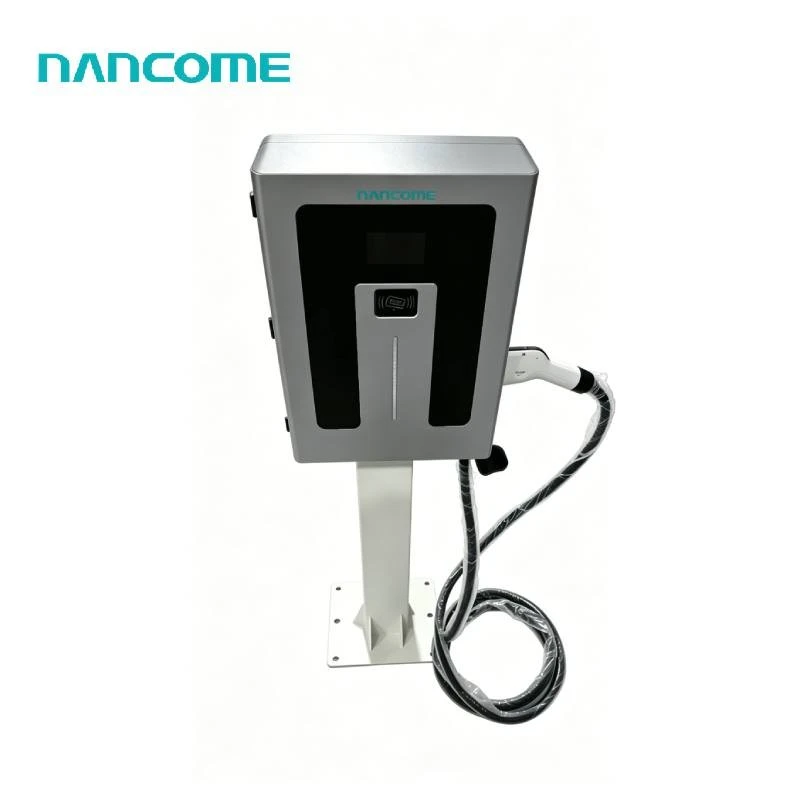
Our floor-mounted NEDF configurations include 40, 60, 80, 120, 160, 180 and 240 kW options with a DC200–1000V output range. Connector configurations can include CCS1, CCS2, GB/T or CHAdeMO according to the project.
A dual-gun DC charger can serve two bays from one cabinet, but buyers must confirm whether the selected configuration supports simultaneous charging, how its internal modules are allocated and how low-power operation is handled. For multiple cabinets, the site controller must coordinate the combined charging limit.
We can discuss charger power, connector arrangement, remote operation and optional OCPP configuration around the target vehicles and site constraints. Final compatibility should be confirmed using vehicle voltage, maximum DC acceptance, connector standard and charging communication requirements.
Project Inputs
Data Required Before Setting Load-Balancing Rules
- Confirm the electrical boundary. Provide transformer rating, available charging capacity, main protection limits and other loads sharing the connection.
- Define the vehicle population. Record battery capacity, operating voltage, maximum DC acceptance, connector type and the number of vehicles.
- Map arrival and departure patterns. Peak concurrency and dwell time are more useful than the total number of vehicles alone.
- Calculate required session energy. State how much energy each vehicle normally needs before its next trip or departure.
- Choose a priority policy. Decide whether charging should be equal, first-come-first-served, departure-based or assigned by vehicle group.
- Specify communication and fallback behavior. Confirm metering, network, backend, OCPP and offline operating requirements.
- Plan commissioning acceptance. Define tests for full concurrency, power redistribution, building-load changes and communication loss.
Common Design Risks
Load Balancing Cannot Correct an Undersized Project
Ignoring Required Energy
A site may stay below its electrical limit yet still fail operationally if vehicles cannot receive enough energy before departure.
Using Nameplate Power Alone
Charger rating does not show how vehicles, internal modules and simultaneous connectors will use power in practice.
No Failure-State Policy
Loss of the meter or control connection must not cause chargers to exceed the site's approved electrical boundary.
Overly Equal Allocation
Equal sharing can delay an urgent fleet vehicle while allocating unnecessary capacity to a vehicle with a long dwell time.
No Expansion Allowance
Metering, communication and distribution design should account for the realistic next phase of chargers and bays.
Untested Interoperability
Protocol support, backend functions and actual charger control must be checked together before project acceptance.
Performance Review
Measure Operational Results After Commissioning
| Metric | What It Reveals | Possible Response |
|---|---|---|
| Site peak demand | Whether charging remains within the intended electrical boundary. | Adjust the site cap, reserve margin or building-load response. |
| Energy delivered before departure | Whether the allocation policy meets vehicle operating needs. | Revise priorities, schedules or installed charging capacity. |
| Connector occupancy | Whether bays are blocked after charging or poorly matched to demand. | Improve operating procedures, access rules or bay quantity. |
| Power curtailment time | How often chargers are limited by the site or building load. | Review transformer capacity, schedules or storage feasibility. |
| Failed or incomplete sessions | Potential communication, compatibility or control problems. | Inspect event records and test the charger, vehicle and backend path. |
The U.S. Department of Energy describes managed charging as controlling when and how vehicles charge while balancing the needs of vehicles, buildings and the grid. Its managed charging guidance for fleets also identifies peak demand, infrastructure cost and grid-capacity constraints as relevant planning concerns.
Related Charging Options
Continue the Site Configuration Process
Smart Charging Control
Review our smart DC EV charger options for connected commercial charging projects.
Backend Integration
Compare communication requirements for an OCPP DC EV charger.
Fleet Operations
Match charging priorities to routes and departures with a fleet EV charging station.
Commercial Sites
Evaluate power, access and operating requirements for a commercial DC EV charging station.
Public Networks
Plan for variable arrivals and multiple users at a public EV charging station.
Installation Planning
Check the installation requirements for DC EV charging stations before equipment selection.
Buyer Questions
DC EV Charging Load Balancing FAQ
No. Load balancing distributes available site power. An individual vehicle remains limited by its battery, state of charge, temperature, voltage platform, connector and maximum DC acceptance. The strategy can improve overall site utilization even when one session does not become faster.
Static balancing assigns fixed limits to chargers or groups. Dynamic balancing adjusts those limits using current charging demand, building consumption or both. Dynamic control can use available capacity more effectively but requires compatible metering, communication and control equipment.
No. The project also needs compatible charger control, metering, a local or central management function, suitable network communication and defined allocation rules. Buyers should verify the required OCPP version, smart-charging functions and backend interoperability.
It may help a project remain within existing capacity when vehicle energy and dwell-time requirements allow controlled charging. It cannot compensate for insufficient energy delivery. A qualified electrical assessment should compare the site limit with peak concurrency and required session energy.
Priority can reflect departure time, route energy, current state of charge, vehicle availability and operational importance. The policy should be based on fleet schedules and tested against the busiest realistic operating period.
The required response must be defined during system design. A project may apply conservative local limits, pause selected chargers or continue within a predetermined safe boundary. This behavior should be verified during commissioning rather than assumed.
Please provide the destination country, site capacity, charger quantity, connector standard, target vehicles, battery voltage, peak simultaneous demand, required energy per session, dwell time, priority rules and OCPP or backend requirements.
Configure Power Allocation Around Your Actual Site Limit
Send us your transformer capacity, building load, target vehicles, charger quantity, peak concurrency, required session energy and management-platform requirements. We will help match the charging hardware and project configuration to the operating conditions.
Request a Load-Balanced Charging Recommendation


